Heat Treatment of Steel
Heat Treating is often associated with increasing the strength of the steel, but it can also be used to alter certain
manufacturability objectives such as improve mach inability, formability, restore ductility etc.
Heat Treatment of Steel
Heat treating of steel is the process of heating and cooling of carbon steel to change the steel's physical and mechanical properties without changing the original shape and size.
Heat Treating is often associated with increasing the strength of the steel, but it can also be used to alter certain manufacturability objectives such as improve mach inability, formability, restore ductility etc. Thus heat treating is a very useful process to help other manufacturing processes and also improve product performance by increasing strength or provides other desirable characteristics. High carbon steels are particularly suitable for heat treatment, since carbon steel respond well to heat treatment and the commercial use of steels exceeds that of any other material.
There are many difference types of heat treating processes, it individual process provides different desirable characteristics to the product.
- Annealing
- Hardening and Tempering of Tool Steels
- Heat Treatment of Low-Alloy Cold-Work Tool Steels
- Heat Treatment of Low-Alloy Cold-Work and Hot-Work Tool Steels
- Surface Hardening of Steels
- Carburizing
- Nitriding
- The Tempering of Martensite
- The tempering of alloys steel
- Gas Nitriding
Annealing
The purpose of anneal heat treating may involve one or more of the following aims:
The treatment is applied to forgings, cold-worked sheets and wire, and castings. The operation consists of: heating the steel to a certain temperature, "soaking" at this temperature for a time sufficient to allow the necessary changes to occur, cooling at a predetermined rate.
Sub-critical Anneal
It is not always necessary to heat the steel into the critical range. Mild steel products which have to be repeatedly cold worked in the processes of manufacture are softened by annealing at 500° to 650°C for several hours. This is known as "process" or "close" annealing, and is commonly employed for wire and sheets. The recrystallisation temperature of pure iron is in the region of 500°C consequently the higher temperature of 650°C brings about rapid recrystallisation of the distorted ferrite Since mild steel contains only a small volume of strained pearlite a high degree of softening is induced. As shown, Fig. 1b illustrates the structure formed consisting of the polyhedral ferrite with elongated pearlite (see also Fig. 2).
Prolonged annealing induces greater ductility at the expense of strength, owing to the tendency of the cementite in the strained pearlite to "ball-up" or spheroidise, as illustrated in Fig. 1c. This is known as "divorced pearlite". The ferrite grains also become larger, particularly if the metal has been cold worked a critical amount. A serious embrittlement sometimes arises after prolonged treatment owing to the formation of cementitic films at the ferrite boundaries. With severe forming operations, cracks are liable to start at these cementite membranes.

Figure 1. Effect of annealing cold-worked mild steel
Figure 2. Effect of annealing at 650°C on worked steel. Ferrite recrystallised. Pearlite remains elongated (x600)
The modern tendency is to use batch or continuous annealing furnaces with an inert purging gas. Batch annealing usually consists of 24-30 hrs 670°C, soak 12 hrs, slow cool 4-5 days. Open coil annealing consists in recoiling loosely with controlled space between wraps and it reduces stickers and discoloration.
Continuous annealing is used for thin strip (85% Red) running at about 400 m/min. The cycle is approximately up to 660°C 20 sec, soak and cool 30-40 sec. There is little chance for grain growth and it produces harder and stiffer strip; useful for cans and panelling.
"Double reduced" steel is formed by heavy reduction (~50%) after annealing but it suffers from directionality. This can be eliminated by heating between 700-920°C and rapidly quenching.
Full Anneal and Normalising Treatments
For steels with less than 0,9% carbon both treatments consist in heating to about 25-50°C above the upper critical point indicated by the Fe-Fe3C equilibrium diagram (Fig. 3). For higher carbon steels the temperature is 50°C above the lower critical point.
Figure 3. Heat-treatment ranges of steels
Average annealing and hardening temperatures are:
|
Carbon, %
|
0.1
|
0.2
|
0.3
|
0.5
|
0.7
|
0.9 to 1.3
|
|
Avg.temp. °C
|
910
|
860
|
830
|
810
|
770
|
760
|
These temperatures allow for the effects of slight variations in the impurities present and also the thermal lag associated with the critical changes. After soaking at the temperature for a time dependent on the thickness of the article, the steel is very slowly cooled. This treatment is known as full annealing, and is used for removing strains from forgings and castings, improving machinability and also when softening and refinement of structure are both required.
Normalising differs from the full annealing in that the metal is allowed to cool in still air. The structure and properties produced, however, varying with the thickness of metal treated. The tensile strength, yield point, reduction of area and impact value are higher than the figures obtained by annealing.
Changes on Annealing
Consider the heating of a 0,3% carbon steel. At the lower critical point (Ac1) each "grain" of pearlite changes to several minute austenite crystals and as the temperature is raised the excess ferrite is dissolved, finally disappearing at the upper critical point (Ac3), still with the production of fine austenite crystals. Time is necessary for the carbon to become uniformly distributed in this austenite. The properties obtained subsequently depend on the coarseness of the pearlite and ferrite and their relative distribution. These depend on:
a) the size of the austenite grains; the smaller their size the better the distribution of the ferrite and pearlite.
b) the rate of cooling through the critical range, which affects both the ferrite and the pearlite.
As the temperature is raised above Ac3 the crystals increase in size. On a certain temperature the growth, which is rapid at first, diminishes. Treatment just above the upper critical point should be aimed at, since the austenite crystals are then small.
By cooling slowly through the critical range, ferrite commences to deposit on a few nuclei at the austenite boundaries. Large rounded ferrite crystals are formed, evenly distributed among the relatively coarse pearlite. With a higher rate of cooling, many ferrite crystals are formed at the austenite boundaries and a network structure of small ferrite crystals is produced with fine pearlite in the centre.
Overheated, Burnt and Underannealed Structures
When the steel is heated well above the upper critical temperature large austenite crystals form. Slow cooling gives rise to the Widmanstätten type of structure, with its characteristic lack of both ductility and resistance to shock. This is known as an overheated structure, and it can be refined by reheating the steel to just above the upper critical point. Surface decarburisation usually occurs during the overheating.
During the Second World War, aircraft engine makers were troubled with overheating (above 1250°C) in drop-stampings made from alloy steels. In the hardened and tempered condition the fractured surface shows dull facets. The minimum overheating temperature depends on the "purity" of the steel and is substantially lower in general for electric steel than for open-hearth steel. The overheated structure in these alloy steels occurs when they are cooled at an intermediate rate from the high temperature. At faster or slower rates the overheated structure may be eliminated. This, together with the fact that the overheating temperature is significantly raised in the presence of high contents of MnS and inclusions, suggests that this overheating is conected in some way with a diffusion and precipitation process, involving MnS. This type of overheating can occur in an atmosphere free from oxygen, thus emphasising the difference between overheating and burning.
As the steel approaches the solidus temperature, incipient fusion and oxidation take place at the grain boundaries. Such a steel is said to be burnt and it is characterised by the presence of brittle iron oxide films, which render the steel unfit for service, except as scrap for remelting.
Hardening and Tempering of Tool Steels
In this text, an example is tool steel W1, designated only by the type letter and numeral as used in the USA and the UK for standardized tool steels. This designation system is so well known by steel consumers all over the world that no qualifying institutional designations are necessary.
Carbon steels and vanadium-alloyed steels
The hardening of these steels, which are made with carbon contents between 0,80% and 1,20%, is quite straightforward: Since the rate of carbide dissolution proceeds rapidly, the holding time, as a consequence, is short and therefore the heating of small tools can often take place without any extra precautions against atmospheric oxidation.
The hardening temperature is about 780°C. Quenching is carried out direct into brine with tempering following immediately. The quenching operation is the most critical part of the heat treatment since too slow a rate of cooling might give rise to either soft spots or quenching cracks.
If the tool is designed to contain hardened areas around holes or reentrant angles the cooling effect must be very intensive at these areas. Manual stirring will often suffice but in many cases the coolant must be sprayed on to the tool. For sections heavier than 20 mm the depth of hardening, i.e. the distance from the surface to the 550 HV level, is about 4 mm. Sections less than about 8 mm in thickness will harden through.
For awkward tools, hardenability may be a crucial factor and under such circumstances the composition of the steel must be adjusted in accordance herewith, in particular as regards the alloying elements Mn and Cr, which have a powerful influence on hardenability.
The diagram in Figure 1 shows how the hardening temperature affects the depth of hardening and fracture number on Wl-type steel of conventional composition. The V-content is only 0,04%, which implies that the steel starts to be coarse-grained when the hardening temperature exceeds 815°C.
Figure 1. Depth of hardening for carbon steel, 25 mm in diameter, corresponding to W1. Quenched in water from various temperatures
In Figure 2 are shown the results of corresponding trials with steel containing somewhat larger amounts of alloying elements. The depth of hardening is considerably greater. Owing to the high content of V the steel remains fine-grained even when hardened from exceptionally high temperatures.
The very considerable toughness inherent in plain-carbon steel, due to its shallow-hardening properties, is forfeited if the tool through-hardens locally at some sections because the cross-sectional area there is too small. For shearing tools or small tools generally, such as scissors, knives or letter die punches, which are not subjected to heavy impact blows, this drawback is of less importance. Tools operating under heavy blows, e.g. upsetting dies for cold-heading of bolts, must not be through-hardened.
Coining and striking punches are other examples of carbon tool steels that require high wear resistance. Such tools may also be subjected to bending stresses and should therefore not be through-hardened. The tempering temperature normally used for tools belonging to this group lies in the range 170°C, the hardness being generally about 60-64 HRC.
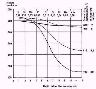
Figure 2. Depth of hardening for carbon steel, 25 mm in diameter, corresponding to W1. Quenched in water from various temperatures
Heat Treatment of Low-Alloy Cold-Work Tool Steels
Two steels have been chosen from this group as examples for the discussion, grade O1 (RT 1733) and Swedish SIS 2092 (SR 1855).
When carbon steel is used for punching dies or cold hobbing tools the dimensions of the tool are bound by a ruling section that is determined by the load on the tool. A punch or a die, made from carbon steel, having a diameter of, say, 50 mm, will show rather poor resistance to sinking on account of the shallow depth of hardening.
Should this resistance not suffice, another steel will have to be chosen, in this case grade O1 or SIS 2092. From the point of view of heat treatment, these two steels differ somewhat since their hardening temperatures are different. Steel SIS 2092 requires 850-890°C whereas grade O1 requires 800-840°C. Owing to its lower hardening temperature, O1 has somewhat greater dimensional stability. This property makes it a first choice for blanking dies and other tools requiring a high degree of dimensional stability (Figure 1).
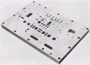
Figure 1. Blanking tool made from steel O1
In both steels the depth of hardening decreases by roughly the same amount as the thickness of the section increases. In the diagram in Figure 2 the hardening temperature was raised as the cross-sectional area increased in order to increase the hardenability of the steel. Tools having diameters greater than about 80 mm or equivalent sections in flat dimensions are difficult to harden to full hardness if there are re-entrant corners. For such designs it is advisable to choose SIS 2092 since it obtains full surface hardness more readily and gives a more regular depth of hardening in a tool with varying section thickness.
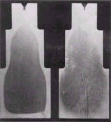
Figure 3. Longitudinal section (etched) through stepped test specimens made from: a) SIS 2092 and b) AISI O1. The diameters are 50, 75 and 100 mm
The above-cited example is to be regarded as a practical assertion of the possibility of estimating the depth of hardening from the Jominy diagram. However, it should be emphasized once again that a `contour-hardened` tool is tougher than a through-hardened one. Figure 4 shows a section through a `contour-hardened` Pilger roll.
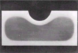
Figure 4. Transverse section through a Pilger roll made from SIS 2092. Size 50x120 mm
As a rule both steels are oil quenched. For heavy sections, e.g. dimensions greater than 100 mm in diameter, it is best to use water quenching when dealing with SIS 2092. When the surface temperature of the steel has fallen to between 400°C and 300°C the water quenching is interrupted by transferring the tool to an oil bath.
The tempering temperature for both steels is generally in the range 170-200°C which gives a hardness of more than 60 HRC. As can be seen from Figure 5, SIS 2092 has a greater resistance to tempering than grade O1.
On being tempered in the range 250-350°C the steel suffers a reduction in its impact strength, which in turn increases the risk of chipping. For this reason tools that are subjected to impact stresses should not be tempered in this temperature range. The higher impact strength manifested after tempering at 170-200°C is due to the presence of retained austenite, viz. about 10%.
Figure 5. Tempering curves for steel O1 and SIS 2092 This soft retained austenite can accommodate impact stresses better than the harder constituents. Retained austenite is decomposed when it is tempered at about 300°C.
If, during service, some areas of the tool have to support excessive pressures, for example the shearing edge of circular slitting knives (see Figure 6), retained austenite may be transformed to martensite, with spalling at the edge as a result. Should this occur, tempering at 300-400°C is recommended. After such a treatment the hardness of SIS 2092 still remains around 60 HRC.
Since the wear resistance of SIS 2092 is as much as 25% greater than that of grade O1, the former is very popular when a wear-resisting steel is required that can give a better performance than grade O1. Compared with this steel, SIS 2092 has been shown to have a considerably longer service life, particularly as drawing die steel.
Another interesting application is as cane-slitting tools (see Figure 7). The requirements of this type of tool are both high wear resistance and toughness in its thin walls. Of all the steels tested the best results were obtained with SIS 2092. In recent years SIS 2092 has increasingly been used for so-called Pilger rolls, which are in part made as rings and in part as dies.
Figure 6. Circular shears (slitting knives) made from SIS 2092
Figure 7. Cane-slitting tool made from SIS 2092
Figure 8 shows one of the world`s largest Pilger rolls, designed for cold-rolling 10 inches tubes. The only steel suitable for this tool was SIS 2092. Another field of application is for what are known as Yoder rolls. A sketch showing the principle of operation and tube manufacture is shown in Figure 9. For this mill unit, the wear resistance of rolls made from SIS 2092 has shown itself to be on a par with that of grade D2, in fact in some instances it has outlasted this grade.
Figure 8. Pilger roll made from SIS 2092 for 10 in tube mill. Dimensions: 800 mm diameter x 400 mm, weight 800 kg
Figure 9. Sketch showing tube-mill operating principle for welded tubes (Yoder mill). Welding stage omitted
This observation is particularly striking when stainless steel tubes are being rolled, since there is no `galling` when SIS 2092 is being used.
Heat Treatment of Low-Alloy Cold-Work and Hot-Work Tool Steels
For considering heat treating this group of material, several typical tool steels are selected as examples, designated only by the type letter and numeral as used in the USA and the UK for standardized tool steels, e.g. H13, O1. These designations are so well known by steel consumers all over the world that no qualifying institutional designations are necessary. Steels for which there are no AISI or BS specifications are designated according to Swedish (SIS) standards.
The hardenability of SIS 2550 is considerably good. SIS 2550 is air heat treated in fairly heavy sections, which is of advantage where dimensional stability is concerned. Due to the lower carbon content the toughness is greater than the most of the other cold-work steels. When used for cold-work tools, the steel is tempered at 170-250°C, the resulting hardness then being 55-58 HRC. With regard to impact strength this steel, too, is susceptible to tempering treatments around 300°C (see Figure 1).
Figure 1. Steel SIS 2550. Hardness and impact strength as functions of tempering temperature
SIS 2550, after hardening and tempering at 200-250°C possesses very high tensile strength and good impact strength. The values given below have been obtained on tensile test specimens that were oil quenched from 830°C and tempered at 250°C.
Such favourable mechanical properties make the steel suitable for tools subjected to large static and dynamic forces. Some typical applications are dies for tableware, shear blades for heavy plate and dies for plastic moulds, which requires steel possessing a high degree of dimensional stability and excellent polishability.
SIS 2550 is also used for hot-work tools working at moderate temperatures, e.g. drop-forging dies. Such tools are tempered between 400°C and 600°C, the exact temperature depending on the hardness required and the working temperature of the tool. For working temperatures above approximately 400°C the hardness of the steel falls relatively quickly.
If higher working temperatures are involved it is recommended to use the special hot-work steels.
Grade S1 has both high wear resistance and high impact strength. The hardenability is inferior to that of the Cr-Ni-Mo steel SIS 2550. This implies that for dimensions greater than 50 mm in diameter, this steel is contour-hardening which, in fact, further increases its toughness.
The normal heat treating temperature is about 900°C but it may be raised to 950°C without any risk of grain growth being incurred. If a hardness higher than 50 HRC is required in dimensions up to about 60 mm in diameter the steel should be quenched in oil. For heavier dimensions a combined water-oil quenching procedure may be necessary.
Of the many cold-work applications for tool steel, special mention should be made of the cold punching of plate having a thickness greater than about 3 mm. If a plate of increasing thickness is being punched and consequently the thickness measurement of the plate is approaching the diameter of the hole, the punches used show an increasing tendency to break if they are made from, for example, grades O1, A2 or D2. For this type of punching work, grade S1 has been shown to possess the best combination of toughness and wear resistance. A suitable hardness is 56-58 HRC.
Wear resistance is further increased if, during the course of the hardening treatment, the tools are heated for some 20 min in a cyanide bath. After this treatment no further finishing is required; at the most a very light finish grinding is permissible. Another example is the use of this steel as the impact hammer in nail guns, used for driving nails into concrete.
Owing to its high toughness in comparatively large dimensions, grade S1 can successfully be used for tableware dies, which, depending on their dimensions should either be quenched in oil or be heat treated according to the combined oil-water quenching procedure.
Another field of application is shear blades for cold shearing of heavy plate. Because of its rather good resistance to tempering, grade S1 may also be used for hot shears, a suitable hardness for this latter use being about 45 HRC.
In the field of hot-work, grade S1 has been superseded by other grades, e.g. H13. However, mention should be made of an interesting and successful field of application for grade S1 -- as chisels used in process of electrolytic reduction of Aluminium from bauxite. The function of the chisels is to break up the hard alumina-containing crust which forms on the metal bath. During their use the chisels also come into contact with the bath itself and are thus subjected to both high temperatures and impact stresses. A suitable chisel hardness is about 350 HB.
Surface Hardening of Steels
Surface hardening a process which includes a wide variety of techniques is used to improve the wear resistance of parts without affecting the softer, tough interior of the part. This combination of hard surface and resistance and breakage upon impact is useful in parts such as a cam or ring gear that must have a very hard surface to resist wear, along with a tough interior to resist the impact that occurs during operation. Further, the surface hardening of steels has an advantage over through hardening because less expensive low-carbon and medium-carbon steels can be surface hardened without the problems of distortion and cracking associated with the through hardening of thick sections.
There are two distinctly different approaches to the various methods for surface hardening (Table 1): methods that involve an intentional buildup or addition of a new layer and methods that involve surface and subsurface modification without any intentional buildup or increase in part dimensions.
Table 1. Engineering methods for surface hardening of steels.
|
Layer
additions
|
Substrate
treatment
|
|
Hardfacing Coatings
Electrochemical plating |
Diffusion methods Selective hardening methods
Flame hardening |
The first group of surface hardening methods includes the use of thin films, coatings, or weld overlays (hard-facings). Films, coatings, and overlays generally become less cost effective as production quantities increase, especially when the entire surface of work pieces must be hardened.
The fatigue performance of films, coatings, and overlays may also be a limiting factor, depending on the bond strength between the substrate and the added layer. Fusion-welded overlays have strong bonds, but the primary surface-hardened steels used in wear applications with fatigue loads include heavy case-hardened steels and flame or induction-hardened steels. Nonetheless, coatings and overlays can be effective in some applications. For tool steels, for example, TiN and Al2O3 coatings are effective not only because of their hardness but also because their chemical inertness reduces wear and the welding of chips to the tool. Overlays can be effective when the selective hardening of large areas is required.
The second group of methods on surface hardening is further divided into diffusion methods and selective hardening methods. Diffusion methods modify the chemical composition of the surface with hardening species such as carbon, nitrogen, or boron. Diffusion methods allow effective hardening of the entire surface of a part and are generally used when a large number of parts are to be surface hardened. In contrast, selective surface hardening methods allow localized hardening. Selective hardening generally involves transformation hardening (from heating and quenching), but some selective hardening methods (selective nitriding, ion implantation and ion beam mixing) are based solely on compositional modification.
As previously mentioned, surface hardening by diffusion involves the chemical modification of a surface. The basic process used is thermo-chemical because some heat is needed to enhance the diffusion of hardening species into the surface and subsurface regions of part.
The depth of diffusion exhibits time-temperature dependence such that:
Case depth ˜ K vTime
where the diffusivity constant, K, depends on temperature, the chemical composition of the steel, and the concentration gradient of a given hardening species. In terms of temperature, the diffusivity constant increases exponentially as a function of absolute temperature. Concentration gradients depend on the surface kinetics and reactions of a particular process.
Methods of hardening by diffusion include several variations of hardening species (such as carbon, nitrogen, or boron) and of the process method used to handle and transport the hardening species to the surface of the part. Process methods for exposure involve the handling of hardening species in forms such as gas, liquid, or ions. These process variations naturally produce differences in typical case depth and hardness (Table 2). Factors influencing the suitability of a particular diffusion method include the type of steel (Table 3).
It is also important to distinguish between total case depth and effective case depth. The effective case depth is typically about two-thirds to three-fourths the total case depth. The required effective depth must be specified so that the heat treatment can process the parts for the correct time at the proper temperature.
Table 2: Typical characteristics of diffusion treatments
| Process | Nature of case | Process temperature (°C) | Typical case depth | Case hardness (HRC) | Typical base metals |
| Carburizing Pack | Diffused carbon | 815-1090 | 125µm-1.5mm | 50-63* | Low-carbon steels, low-carbon alloy steels |
Gas |
Diffused carbon | 815-980 |
75 µm-1.5mm |
50-63* | Low-carbon steels, low-carbon alloy steels |
| Liquid | Diffused carbon and possibly nitrogen | 815-980 | 50 µm-1.5mm | 50-65* | Low-carbon steels, low-carbon alloy steels |
| Vacuum | Diffused carbon | 815-1090 | 75 µm-1.5mm |
50-63* | Low-carbon steels, low-carbon alloy steels |
| Nitriding Gas | Diffused nitrogen,nitrogen compounds | 480-590 | 12µm-0.75mm |
50-70 | Alloy steels, nitriding steels, stainless steels |
| Salt | Diffused nitrogen, nitrogen compounds |
510-565 | 2.5µm-0.75mm | 50-70 | Most ferrous metals. Including cast irons |
| Ion | Diffused nitrogen. nitrogen compounds |
340-565 | 75µm-0.75mm | 50-70 | Alloy steels, nitriding steels, stainless steels |
| Carbonitriding Gas | Diffused carbon and nitrogen | 760-870 | 75µm-0.75mm | 50-65* | Low-carbon steels, low-carbon alloy steels, stainless steels |
| Liquid (cyaniding) | Diffused carbon and nitrogen | 760-870 | 2.5-125µm | 50-65* | Low-carbon steels |
Ferritic nitrocarburizing |
Diffused carbon and nitrogen | 565-675 | 2.5-25µm | 40-60* | Low-carbon steels |
| Other Aluminizing (pack) | Diffused aluminum | 870-980 | 25µm-1mm | < 20 | Low-carbon steels |
| Siliconizing by chemical vapor deposition | Diffused silicon | 925-1040 | 25µm-1mm | 30-50 | Low-carbon steels |
| Chromizing by chemical vapor deposition | Diffused chromium | 980-1090 | 25-50µm | Low-carbon steel < 30; High-carbon 50-60 | High- and low carbon steels |
| Titanium Carbide | Diffused carbon and titanium, TiC compound | 900-1010 | 2,5-12.5µm | > 70* | Alloy steels, tool steels |
* Requires quench from austenitizing temperature.
Table 3. Types of steels used for various diffusion processes
|
Diffusion
substrates
|
|||
|
Low-carbon
steels
|
Alloy steels
|
Tool steels
|
Stainless
steels
|
| Carburizing Cyaniding Ferritic nitrocarburizing Carbonitriding |
Nitriding Ion nitriding |
Titanium carbide Boriding Salt nitriding Ion nitriding Gas nitriding |
Gas nitriding Titanium carbide Ion nitriding Ferritic nitrocarburizing |
Carburizing
Carburizing or case hardning is the addition of carbon to the surface of low-carbon steels at temperatures generally between 850 and 950°C (1560 and 1740°F), at which austenite, with its high solubility for carbon, is the stable crystal structure. Hardening is accomplished when the high-carbon surface layer is quenched to form martensite so that a high-carbon martensitic case with good wear and fatigue resistance is superimposed on a tough, low-carbon steel core.
Case hardness of carburized steels is primarily a function of carbon content. When the carbon content of the steel exceeds about 0.50% additional carbon has no effect on hardness but does enhance hardenability. Carbon in excess of 0.50% may not be dissolved, which would thus require temperatures high enough to ensure carbon-austenite solid solution.
Case hardening depth of carburized steel is a function of carburizing time and the available carbon potential at the surface. When prolonged carburizing times are used for deep case depths, a high carbon potential produces a high surface-carbon content, which may thus result in excessive retained austenite or free carbides. These two microstructural elements both have adverse effects on the distribution of residual stress in the case-hardened part. Consequently, a high carbon potential may be suitable for short carburizing times but not for prolonged carburizing.
Carburizing steels for case hardening usually have base-carbon contents of about 0.2%, with the carbon content of the carburized layer generally being controlled at between 0.8 and 1% C. However, surface carbon is often limited to 0.9% because too high a carbon content can result in retained austenite and brittle martensite.
Most steels that are carburized are killed steels (deoxidized by the addition of aluminum), which maintain fine grain sizes to temperatures of about 1040°C. Steels made to coarse grain practices can be carburized if a double quench provides grain refinement. Double quenching usually consists of a direct quench and then a requench from a lower temperature.
Many alloy steels for case hardening are now specified on the basis of core hardenability. Although the same considerations generally apply to the selection of uncarburized grades, there are some peculiarities in carburizing applications.
First, in a case-hardened steel, the hardenability of both case and core must be considered. Because of the difference in carbon content, case and core have quite different hardenabilities, and this difference is much greater for some steels than for others.
Moreover, the two regions have different in-service functions to perform. Until the introduction of lean alloy steels such as the 86xx series, with and without boron, there was little need to be concerned about case hardenability because the alloy content combined with the high carbon content always provided adequate hardenability. This is still generally true when the steels are direct quenched from carburizing, so that the carbon and alloying elements are in solution in the case austenite. In parts that are reheated for hardening and in heavy-sectioned parts, however, both case and core hardenability requirements should be carefully evaluated.
The relationship between the thermal gradient and the carbon gradient during quenching of a carburized part can make a measurable difference in the case depth as measured by hardness. That is, an increase in base hardenability can produce a higher proportion of martensite for a given carbon level, yielding an increased measured case depth. Therefore, a shallower carbon profile and shorter carburizing time could be used to attain the desired result in a properly chosen steel.
Core Hardness. A common mistake is to specify too narrow a range of core hardness. When the final quench is from a temperature high enough to allow the development of full core hardness, the hardness variation at any location will be that of the hardenability band of the steel at the corresponding position on the end-quenched hardenability specimen.
In standard steels purchased to chemical composition requirements rather than to hardenability, the range can be 20 or more HRC points; for example, 8620 may vary from 20 to 45 HRC at the 4/16 in.(6.35mm) position. The 25-point range emphasizes the advantage of purchasing to hardenability specifications to avoid the intolerable variation possible within the ranges for standard chemistry steels. Another way to control core hardness within narrow limits without resorting to the use of high-alloy steels is to use a final quench from a lower temperature so that full hardness in the case will be developed without the disadvantage of excessive core hardness.
Gears are almost always oil quenched because distortion must be held to the lowest possible level. Therefore, alloy steels are usually selected, with much debate about which particular alloy. The lower-alloy steels such as 4023, 5120, 4118, 8620, and 4620, with a carbon range between 0.15 and 0.25%, are widely used and generally satisfactory. Usually, the first choice is one of the last two steels mentioned, either of which should be safe for all ordinary applications. The final choice, based on service experience or dynamometer testing, should be the least expensive steel that will do the job. For heavy-duty applications, higher-alloy grades such as 4320, 4817, and 9310 are justifiable if based on actual performance tests. The life testing of gears in the same mountings used in service to prove both the design and the steel selection is particularly important.
In other applications, when distortion is not a major factor, the carbon steels described above, water quenched, can be used up to a 50 mm (2 in.) diameter. In larger sizes, low-alloy steels, water quenched, such as 5120, 4023, and 6120 can be used, but possible distortion and quench cracking must be avoided.
Carburizing Methods. While the basic principle of carburizing has remained unchanged since carburizing was first employed, the method used to introduce the carbon into the steel has been a matter of continuous evolution.
In its earliest application, parts were simply placed in a suitable container and covered with a thick layer of carbon powder (pack carburizing). Although effective in introducing carbon, this method was exceedingly slow, and as the demand for greater production grew, a new process using a gaseous atmosphere was developed.
In gas carburizing, the parts are surrounded by a carbon-bearing atmosphere that can be continuously replenished so that a high carbon potential can be maintained. While the rate of carburizing is substantially increased in the gaseous atmosphere, the method requires the use of a multicomponent atmosphere whose composition must be very closely controlled to avoid deleterious side effects, for example, surface and grain-boundary oxides. In addition, a separate piece of equipment is required to generate the atmosphere and control its composition. Despite this increased complexity, gas carburizing has become the most effective and widely used method for carburizing steel parts in large quantities.
In efforts required to simplify the atmosphere, carburizing in an oxygen-free environment at very low pressure (vacuum carburizing) has been explored and developed into a viable and important alternative. Although the furnace enclosure in some respects becomes more complex, the atmosphere is greatly simplified. A single-component atmosphere consisting solely of a simple gaseous hydrocarbon, for example methane, may be used. Furthermore, because the parts are heated in an oxygen-free environment, the carburizing temperature may be increased substantially without the risk of surface or grain-boundary oxidation. The higher temperature permitted increases not only the solid solubility of carbon in the austenite but also its rate of diffusion, so that the time required to achieve the case depth desired is reduced.
Although vacuum carburizing overcomes some of the complexities of gas carbunzing, it introduces a serious new problem that must be addressed. Because vacuum carburizing is conducted at very low pressures, and the rate of flow of the carburizing gas into the furnace is very low, the carbon potential of the gas in deep recesses and blind holes is quickly depleted. Unless this gas is replenished, a great nonuniformity in case depth over the surface of the part is likely to occur. If, in an effort to overcome this problem, the gas pressure is increased significantly, another problem arises, that of free-carbon formation, or sooting.
Thus, in order to obtain cases of reasonably uniform depth over a part of complex shape, the gas pressure must be increased periodically to replenish the depleted atmosphere in recesses and then reduced again to the operating pressure. Clearly, a delicate balance exists in vacuum carburizing: The process conditions must be adjusted to obtain the best compromise between case uniformity, risk of sooting, and carburizing rate.
A method that overcomes both of these major problems, yet retains the desirable features of a simple atmosphere and permissible operating temperature is plasma or ion carburizing.
To summarize, carburizing methods include:
These methods introduce carbon by the use of gas (atmospheric-gas, plasma, and vacuum carburizing), liquids (salt bath carburizing), or solid compounds (pack carburizing). All of these methods have limitations and advantages, but gas carburizing is used most often for large-scale production because it can be accurately controlled and involves a minimum of special handling.
Vacuum carbunzing and plasma carburizing have found applications because of the absence of oxygen in the furnace atmosphere. Salt bath and pack carburizing arc still done occasionally, but have little commercial importance today.
Process characteristics of the above-mentioned carburizing methods fall into two general groups:
Conventional methods, which introduce carbon by gas atmospheres, salt baths or charcoal packs Plasma methods, which impinge positive carbon ions on the surface of a steel part (the cathode) The main difference between conventional and plasma methods is the reduced carburizing times achieved in plasma-assisted methods. The quickly attained surface saturation also results in faster diffusion kinetics. Furthermore, plasma carburizing produces very uniform case depths, even in parts with irregular surfaces. With the conventional methods, carburization always takes place by means of a gaseous phase of carbon monoxide; however, each method also involves different reaction and surface kinetics, producing different case-hardening results.
In general, with conventional methods, carbon monoxide breaks down at the steel surface:
2CO ? CO2 + C
The liberated carbon is readily dissolved by the austenite phase and diffuses into the body of the steel. For some process methods (gas and pack carburizing), the carbon dioxide produced may react with the carbon atmosphere or pack charcoal to produce new carbon monoxide by the reverse reaction.
Carburizing is most frequently performed between 850 and 950°C (1550 and 1750°F), but sometimes higher temperatures are used to reduce cycle times and/or produce deeper depths of the high-carbon surface layer.
A comprehensive model of gas carburization must include algorithms that describe:
Nitriding
Nitriding is a surface-hardening heat treatment that introduces nitrogen into the surface of steel at a temperature range (500 to 550°C, or 930 to 1020°F), while it is in the ferrite condition. Thus, nitriding is similar to carburizing in that surface composition is altered, but different in that nitrogen is added into ferrite instead of austenite. Because nitriding does not involve heating into the austenite phase field and a subsequent quench to form martensite, nitriding can be accomplished with a minimum of distortion and with excellent dimensional control.
The mechanism of nitriding is generally known, but the specific reactions that occur in different steels and with different nitriding media are not always known. Nitrogen has partial solubility in iron. It can form a solid solution with ferrite at nitrogen contents up to about 6%. At about 6% N, a compound called gamma prime (?’), with a composition of Fe4N is formed.
At nitrogen contents greater than 8%, the equilibrium reaction product is e compound, Fe3N. Nitrided cases are stratified. The outermost surface can be all ?’ and if this is the case, it is referred to as the white layer. Such a surface layer is undesirable: it is very hard profiles but is so brittle that it may spall in use. Usually it is removed; special nitriding processes are used to reduce this layer or make it less brittle. The e zone of the case is hardened by the formation of the Fe3N compound, and below this layer there is some solid solution strengthening from the nitrogen in solid solution.
Principal reasons for nitriding are:
Nitridable Steels
Nitrided steels are generally medium-carbon (quenched and tempered) steels that contain strong nitride-forming elements such as aluminum, chromium, vanadium, and molybdenum.
The most significant hardening is achieved with a class of alloy steels (nitralloy type) that contain about 1% Al. When these steels are nitrided the aluminum forms AlN particles, which strain the ferrite lattice and create strengthening dislocations. Titanium and chromium are also used to enhance case hardness although case depth decreases as alloy content increases.
Of the alloying elements commonly used in commercial steels, aluminum, chromium, vanadium, tungsten and molybdenum are beneficial in nitriding because they form nitrides that are stable at nitriding temperatures. Molybdenum in addition to its contribution as a nitride former also reduces the risk of embrittlement at nitriding temperatures. Other alloying elements such as nickel, copper, silicon and manganese have little, if any, effect on nitriding characteristics.
Although at suitable temperatures all steels are capable of forming iron nitrides in the presence of nascent nitrogen, the nitriding results are more favorable in those steels that contain one or more of the major nitride-forming alloying elements. Because aluminum is the strongest nitride former of the common alloying elements, aluminum containing steels (0.85 to 1.50% Al) yield the best nitriding results in terms of total alloy content.
The following steels can be gas nitrided for specific applications:
Nitriding processes
Process methods for nitriding include:
The advantages and disadvantages of these techniques are similar to those of carburizing. However, times for gas nitriding can be quire long, that is, from 10 to 130 h depending on the application, and the case depths are relatively shallow, usually less than 0.5 mm. Plasma nitriding allows faster nitriding times, and the quickly attained surface saturation of the plasma process results in faster diffusion. Plasma nitriding can also clean the surface by sputtering.
Gas Nitriding
Gas nitriding is a case-hardening process whereby nitrogen is introduced into the surface of a solid ferrous alloy by holding the metal at a suitable temperature in contact with a nitrogenous gas, usually ammonia. Quenching is not required for the production of a hard case. The nitriding temperature for all steels is between 495 and 565°C.
Because of the absence of a quenching requirement with attendant volume changes, and the comparatively low temperatures employed in this process, nitriding of steels produces less distortion and deformation than either carburizing or conventional hardening. Some growth occurs as a result of nitriding but volumetric changes are relatively small.
Prior Heat Treatment. All hardenable steels must be hardened and tempered before being nitrided. The tempering temperature must be high enough to guarantee structural stability at the nitriding temperature: the minimum tempering temperature is usually at least 30°C (50°F) higher than the maximum temperature to be used in nitriding.
Single-Stage and Double-Stage Nitriding. Either a single- or a double-stage process may be employed when nitriding with anhydrous ammonia. In the single-stage process, a temperature in the range of about 495 to 525°C is used and the dissociation rate ranges from 15 to 30%. This process produces a brittle nitrogen-rich layer known as the white nitride layer at the surface of the nitrided case.
The double-stage process, known also as the Floe process, has the advantage of reducing the thickness of the white nitrided layer.
The first stage of the double-stage process is, except for time, a duplication of the single-stage process. The second stage may proceed at the nitriding temperature employed for the first stage or the temperature may be increased to from 550 to 565°C; however, at either temperature, the rate of dissociation in the second stage is increased to 65 to 80% (preferably 75 to 80%). Generally, an external ammonia dissociator is necessary for obtaining the required higher second-stage dissociation.
The principal purpose of double-stage nitriding is to reduce the depth of the white layer produced on the surface of the case. Except for a reduction in the amount of ammonia consumed per hour, there is no advantage in using the double-stage process unless the amount of white layer produced in single-stage nitriding cannot be tolerated on the finished part or unless the amount of finishing required after nitriding is substantially reduced.
To summarize, the use of a higher temperature during the second stage:
Bright Nitriding
Bright nitriding is a modified form of gas nitriding employing ammonia and hydrogen gases. Atmosphere gas is continually withdrawn from the nitriding furnace and passed through a temperature-controlled scrubber containing a water solution of sodium hydroxide (NaOH). Trace amounts of hydrogen cyanide (HCN) formed in the nitriding furnaces are removed in the scrubber thus improving the rate of nitriding.
The scrubber also establishes a predetermined moisture content in the nitriding atmosphere reducing the rate of cyanide formation and inhibiting the cracking of ammonia to molecular nitrogen and hydrogen. By this technique control over the nitrogen activity of the furnace atmosphere is enhanced and nitrided parts can be produced with little or no white layer at the surface. If present, the white layer will be composed of only the more ductile Fe4N (gamma prime) phase.
Pack Nitriding
Pack nitriding is a process analogous to pack carburizing. It employs certain nitrogen-bearing organic compounds as a source of nitrogen. Upon heating, the compounds used in the process form reaction products that are relatively stable at temperatures up to 570°C.
Slow decomposition of the reaction products at the nitriding temperature provides a source of nitrogen. Nitriding times of 2 to 16 h can be employed. Pans are packed in glass ceramic or aluminum containers with the nitriding compound, which is often dispersed in an inert packing media.
Ion (or Plasma) Nitriding
Since the mid-1960s, nitriding equipment utilizing the glow-discharge phenomenon has been commercially available. Initially termed glow-discharge nitriding, the process is now generally known as ion, or plasma, nitriding. The term plasma nitriding is gaining acceptance.
Ion nitriding is an extension of conventional nitriding processes using plasma-discharge physics. In vacuum, high-voltage electrical energy is used to form a plasma, through which nitrogen ions are accelerated to impinge on the workpiece. This ion bombardment heats the workpiece, cleans the surface, and provides active nitrogen.
Metallurgically versatile, the process provides excellent dimensional control and retention of surface finish. Ion nitriding can be conducted at temperatures lower than those conventionally employed. Control of white-layer composition and thickness enhances fatigue properties. The span of ion-nitriding applications includes conventional ammonia- gas nitriding, short-cycle nitriding in salt bath or gas, and the nitriding of stainless steels.
Ion nitriding lends itself to total process automation, ensuring repetitive metallurgical results. The absence of pollution and insignificant gas consumption are important economic and public policy factors. Moreover, selective nitriding accomplished by simple masking techniques may yield significant economies.
Comparison of Ion Nitriding and Ammonia-Gas Nitriding
Ammonia-gas nitriding produces a compound zone that is a mixture of both epsilon and gamma-prime structures. High internal stresses result from differences in volume growth associated with the formation of each phase. The interfaces between the two crystal structures are weak. Thicker compound zones, formed by ammonia-gas nitriding, limit accommodation of the internal stresses resulting from the mixed structure.
Under cyclic loading, cracks in the compound zone can serve as initiation points for the propagation of fatigue cracks. The single-phase gamma-prime compound zone, which is thin and more ductile, exhibits superior fatigue properties. Reducing the thickness of the ion-nitrided compound zone further improves fatigue performance. Maximization occurs at the limiting condition, where compound zone depth equals zero.
Case Hardness. The bulk of the thickness of the nitride case is the diffusion zone where fine iron/alloy nitride precipitates impart increased hardness and strength. Compressive stresses are also developed, as in other nitriding processes. Hardness profiles resulting from ion nitriding are similar to ammonia-gas nitriding but near-surface hardness may be greater with ion nitriding, a result of lower processing temperature.
Advantages and Disadvantages of Ion Nitriding. Ion nitriding achieves repetitive metallurgical results and complete control of the nitrided layers. This control results in superior fatigue performance, wear resistance, and hard layer ductility. Moreover, the process ensures high dimensional stability, eliminates secondary operations, offers low operating-temperature capability and produces parts that retain surface finish.
Among operating benefits are:
Reduced nitriding time
The limitations of ion nitriding include high capital cost, need for precision fixturing with electrical connections, long processing times compared to other short-cycle nitrocarburizing processes, and lack of feasibility of liquid quenching for carbon steels.
The Tempering of Martensite
Martensite is a very strong phase but it is normally very brittle so it is necessary to modify the mechanical properties by heat treatment in the range 150-700°C. This process, which is called tempering, is one of the oldest heat treatments applied to steels although it is only in recent years that a detailed understanding of the phenomena involved has been reached.
Essentially, martensite is a highly supersaturated solid solution of carbon in iron, which, during tempering, rejects carbon in the form of finely divided carbide phases. The end result of tempering is a fine dispersion of carbides in an a-iron matrix, which often bears little structural similarity to the original as-quenched martensite.
It should be noted that, in many steels, the martensite reaction does not go to completion on quenching, resulting in varying amounts of retained austenite which does not remain stable during the tempering process.
Tempering of plain carbon steels
The as-quenched martensite possesses a complex structure. This occurs in the first-formed martensite, i.e. the martensite formed near Ms, which has the opportunity of tempering during the remainder of the quench. This phenomenon, which is referred to as auto-tempering, is clearly more likely to occur in steels with a high Ms.
On reheating as-quenched martensite, the tempering takes place in four distinct but overlapping stages:
Tempering stage 1
Martensite formed in medium and high carbon steels (0.3-1.5% C) is not stable at room temperature because interstitial carbon atoms can diffuse in the tetragonal martensite lattice at this temperature. This instability-increases between room temperature and 2500°C, when iron carbide precipitates in the martensite.
Tempering stage 2
During stage 2, austenite retained during quenching is decomposed, usually in the temperature range 230-300°C. Cohen and coworkers detected this stage by X-ray diffraction measurements as well as dilatometric and specific volume measurements. However, the direct observation of retained austenite in the microstructure has always been rather difficult, particularly if it is present in low concentrations. The little available evidence suggests that in the range 230-300°C, retained austenite decomposes to bainite, ferrite and cementite, but no detailed comparison between this phase and lower bainite has yet been made.
Tempering stage 3
During the Third stage of tempering, cementite first appears in the microstructure as a Widmanstatten distribution of rods, which have a well-defined orientation relationship with the matrix which has now lost its tetragonality and become ferrite.
This reaction commences as low as 100°C, and is fully developed at 300°C, with particles up to 200 nm long and ~15 nm in diameter. Similar structures are often observed in lower carbon steels as quenched, as a result of the formation of Fe3C during the quench. During tempering, the replacement of transition carbides and low-temperature martensite by cementite and ferrite. During the third stage of tempering the tetragonality of the matrix disappears and it is then, essentially, ferrite, not supersaturated with respect to carbon. Subsequent changes in the morphology of the cementite particles occur by an Ostwald ripening type of process, where the smaller particles dissolve in the matrix providing carbon for the selective growth of the larger particles.
Tempering stage 4
It is useful to define a fourth stage of tempering in which the cementite particles undergo a coarsening process and essentially lose their crystallographic morphology, becoming spheroidized. The coarsening commences between 300 and 400°C, while spheroidization takes place increasingly up to 700°C. At the higher end of this range of temperature the martensite lath boundaries are replaced by more equiaxed ferrite grain boundaries by a process which is best described as recrystallization. The final result is an equiaxed array of ferrite grains with coarse spheroidized particles of Fe3C partly, but not exclusively, in the grain boundaries.
The spheroidization of the Fe3C rods is encouraged by the resulting decrease in surface energy. The particles, which preferentially grow and spheroidize are located mainly at interlath boundaries and prior austenite boundaries, although some particles remain in the matrix. The boundary sites are preferred because of the greater ease of diffusion in these regions. The original martensite lath boundaries remain stable up to about 600°C, but in the range 350-600°C, there is considerable rearrangement of the dislocations within the laths and at those lath boundaries which are essentially low angle boundaries.
Role of carbon content
Carbon has a profound effect on the behavior of steels during tempering. Firstly, the hardness of the as-quenched martensite is largely influenced by the carbon content, as is the morphology of the martensite laths which have a {111} habit plane up to 0.3 % C, changing to {225} at higher carbon contents.
The Ms temperature is reduced as the carbon content increases, and thus the probability of the occurrence of auto-tempering is less. During fast quenching in alloys with less than 0.2 % C, the majority (up to 90%) of the carbon segregates to dislocations and lath boundaries, but with slower quenching some precipitation of cementite occurs.
On subsequent tempering of low carbon steels up to 200°C further segregation of carbon takes place, but no precipitation has been observed. Under normal circumstances it is difficult to detect any tetragonality in the martensite in steels with less than 0.2 % C, a fact which can also be explained by the rapid segregation of carbon during quenching.
Mechanical properties of tempered plain carbon steels
The intrinsic mechanical properties of tempered plain carbon martensitic steels are difficult to measure for several reasons. Firstly, the absence of other alloying elements means that the hardenability of the steels is low, so a fully martensitic structure is only possible in thin sections. However, this may not be a disadvantage where shallow hardened surface layers are all that is required. Secondly, at lower carbon levels, the Ms temperature is rather high, so tempering is likely to take place. Thirdly, at the higher carbon levels the presence of retained austenite will influence the results. Added to these factors, plain carbon steels can exhibit quench cracking which makes it difficult to obtain reliable test results. This is particularly the case at higher carbon levels, i.e. above 0.5% carbon.
Provided care is taken, very good mechanical properties, in particular proof and tensile stresses, can be obtained on tempering in the range 100-300°C. However, the elongation is frequently low and the impact values poor. Plain carbon steels with less than 0.25% C are not normally quenched and tempered, but in the range 0.25-0.55 % C heat treatment is often used to upgrade mechanical properties.
The usual tempering temperature is between 300 and 700°C allowing the development of tensile strengths between 1700 and 800 MPa, the toughness increasing as the tensile strength decreases. This group of steels is very versatile as they can be used for crankshafts and general machine parts as well as hand tools, such as screwdrivers and pliers.
The high carbon steels (0.5-1.0%) are much more difficult to fabricate and are, therefore, particularly used in applications where high hardness and wear resistance are required, e.g. axes, knives, hammers, cutting tools. Another important application is for springs, where often the required mechanical properties are obtained simply by heavy cold work, i.e. hard drawn spring wire. However, carbon steels in the range 0.5-0.75% C are quenched, and then tempered to the required yield stress.
The tempering of alloys steel
The addition of alloying elements to steel has a substantial effect on the kinetics of the transformation, and also of the pearlite reaction. Most common alloying elements move the TTT curves to longer times, with the result that it is much easier to "miss" the nose of the curve during quenching. This essentially gives higher hardenability, since martensite structures can be achieved at slower cooling rates and, in practical terms, thicker specimens can be made fully martensitic.
Alloying elements have also been shown to have a substantial effect in depressing the Ms temperature. In this section, we will examine the further important effects of alloying elements during the tempering of martensite, where not only the kinetics of the basic reactions are influenced but also the products of these reactions can be substantially changed, e.g. cementite can be replaced by other carbide phases. Several of the simpler groups of alloy steels will be used to provide examples of the general behavior.
The effect of alloying elements on the formation of iron carbides
The structural changes during the early stage of tempering are difficult lo follow. However, it is clear that certain elements, notably silicon, can stabilize the carbide to such an extent that it is still present in the microstructure after tempering at 400°C in steels with 1-2% Si, and at even higher temperatures if the silicon is further increased.
While the tetragonality of martensite disappears by 300°C in plain carbon steels, in steels containing some alloying elements, e.g. Cr, Mo, W, V, Ti, Si, the tetragonal lattice is still observed after tempering at 450°C and even as high as 500°C. It is clear that these alloying elements increase the stability of the supersaturated iron-carbon solid solution. In contrast manganese and nickel decrease the stability.
Alloying elements also greatly influence the proportion of austenite retained on quenching. Typically, a steel with 4% molybdenum, 0.2% C, in the martensitic state contains less than 2% austenite, and about 5% is detected in a steel with 1% vanadium and 0.2% C. On tempering each of the above steels at 300°C, the austenite decomposes to give thin grain boundary films of cementite which, in the case of the higher concentrations of retained austenite, can be fairly continuous along the lath boundaries. It is likely that this interlace cementite is responsible for tempered martensite embrittlement, frequently encountered as a toughness minimum in the range 300-350°C, by leading to easy nucleation of cracks, which then propagate across the tempered martensite laths.
Alloying elements can also restrain the coarsening of cementite in the range 400-700°C, a basic process during the fourth stage of tempering. Several alloying elements, notably silicon, chromium, molybdenum and tungsten, cause the cementite to retain its fine Widmanstatten structure to higher temperatures, either by entering into the cementite structure or by segregating at the carbide-ferrite interfaces. Whatever the basic cause may be, the effect is to delay significantly the softening process during tempering. This influence on the cementite dispersion has other effects, in so far as the carbide particles, by remaining finer, slow down the reorganization of the dislocations inherited from the martensite, with the result that the dislocation substructures refine more slowly. The cementite particles are also found on ferrite grain boundaries, where they control the rate at which the ferrite grains grow.
In plain carbon steels cementite particles begin to coarsen in the temperature range 350-400°C, and addition of chromium, silicon, and molybdenum or tungsten delays the coarsening to the range 500-550°C. It should be emphasized that up to 500°C, the only carbides to form are those of iron. However, they will take varying amounts of alloying elements into solid solution and may reject other alloying elements as they grow.
The formation of alloy carbides: secondary hardening
A number of the familiar alloying elements in steels form carbides, which are thermodynamically more stable than cementite. It is interesting to note that this is also true of a number of nitrides and borides. Nitrogen and boron are increasingly used in steels in small but significant concentrations. The alloying elements Cr, Mo, V, W and Ti all form carbides with substantially higher enthalpies of formation, while the elements nickel, cobalt and copper do not form carbide phases. Manganese is weak carbide former, found in solid solution in cementite and not in a separate carbide phase.
It would, therefore, be expected that when strong carbide forming elements are present in steel in sufficient concentration, their carbides would be formed in preference to cementite. Nevertheless, during the tempering of all alloy steels, alloy carbides do not form until the temperature range 500-600°C, because below this the metallic alloying elements cannot diffuse sufficiently rapidly to allow alloy carbides to nucleate.
The metallic elements diffuse substitutionally, in contrast to carbon and nitrogen which move through the iron lattice interstitially, with the result that the diffusivities of carbon and nitrogen are several orders of magnitude greater in iron, than those of the metallic alloying elements. Consequently, higher temperatures are needed for the necessary diffusion of the alloying elements prior to the nucleation and growth of the alloy carbides and, in practice, for most of the carbide forming elements this is in the range 500-600°C.
This secondary hardening process is a type of age-hardening reaction, in which relatively coarse cementite dispersion is replaced by new and much finer alloy carbide dispersion. On attaining a critical dispersion parameter, the strength of the steel reaches a maximum, and as the carbide dispersion slowly coarsens, the strength drops.
Nucleation and growth of alloy carbides
The dispersions of alloy carbides which occur during tempering can be very complex, but some general principles can be discerned which apply to a wide variety of steels. The alloy carbides can form in at least three ways:
In-site nucleation at pre-existing cementite particles. It has been shown that the nuclei form on the interfaces between cementite particles and the ferrite. As they grow, carbon is provided by the adjacent cementite, which gradually disappears.
By separate nucleation within the ferrite matrix, usually on dislocations inherited from the martensitic structure.
At grain boundaries and sub boundaries-these include the former austenite boundaries, the original martensitic lath boundaries (now ferrite), and the new ferrite boundaries formed by coalescence of sub boundaries, or by recrystallization.
In-site nucleation at pre-existing cementite particles are a common occurrence but because these particles are fairly widely spaced at temperatures above 500°C, the contribution of this type of alloy carbide nucleation to strength is very limited.
The nucleation of carbides at the various types of boundary is to be expected because these are energetically favourable sites, which provide paths for relatively rapid diffusion of solute. Consequently the ageing process is usually more advanced in these regions and the precipitate is more massive. In many alloy steels, the first alloy carbide to form is not the final equilibrium carbide and, in some steels, as many as three alloy carbides can form successively. In these circumstances, the equilibrium alloy carbide frequently nucleates first in the grain boundaries, grows rapidly and eventually completely replaces the Widmanstatten non-equilibrium carbide within the grains.
Tempering of steels containing vanadium
Vanadium is a strong carbide former and, in steel with as little as 0.1% V, the face-centered cubic vanadium carbide VC is formed. It is often not of stoichiometric composition, being frequently nearer V4C3, but with other elements in solid solution within the carbide. Normally, this is the only vanadium carbide formed in steels, so the structural changes during tempering of vanadium steels are relatively simple.
Tempering of steels containing molybdenum and tungsten
When molybdenum or tungsten is the predominant alloying element in a steel, a number of different carbide phases are possible, but for composition between 4 and 6 wt% of the element the carbide sequence is likely to be: Fe3C- Mo3C- W2C.
The carbides responsible for the secondary hardening in both the case of tungsten and molybdenum are the isomorphous hexagonal carbides Mo3C and W2C, both of which, in contrast to vanadium carbide, have a well-defined rod let morphology.
Complex alloy steels
The presence of more than one carbide-forming element can complicate the precipitation processes during tempering. In general terms, the carbide phase which is the most stable thermodynamically will predominate, but this assumes that equilibrium is reached during tempering. This is clearly not so at temperatures below 500-600°C. The use of pseudo-binary diagrams for groups of steels, e.g. Cr-V, Cr-Mo, can be a useful guide to carbide phases likely to form during tempering.
Certain strong carbide formers, notably niobium, titanium and vanadium, have effects on tempering out of proportion to their concentration. In concentrations of 0.1 wt % or less, provided the tempering temperature is high enough, i.e. 550-650°C, they combine preferentially with part of the carbon and, in addition to the major carbide phase, e.g. Cr7C3, Mo2C, they form a separate, very much finer dispersion, more resistant to over-ageing.
This secondary dispersion can greatly augment the secondary hardening reaction, illustrating the importance of these strong carbide forming elements in achieving high strength levels, not only at room temperature but also at elevated temperatures, where creep resistance is often an essential requirement.
Gas Nitriding
Gas nitriding is a case-hardening process whereby nitrogen is introduced into the surface of a solid ferrous alloy by holding the metal at a suitable temperature in contact with a nitrogenous gas, usually ammonia. The nitriding temperature for all steels is between 495 and 565°C (925 and 1050°F).
Principal reasons for nitriding are:
To obtain high surface hardness
To increase wear resistance and antigalling properties
To improve fatigue life
To improve corrosion resistance
To obtain a surface that is resistant to the softening effect of heat at temperatures up to the nitriding temperature.
Because of the absence of a quenching requirement, with attendant volume changes, and the comparatively low temperatures employed in this process, nitriding of steels produces less distortion and deformation than either carburizing or conventional hardening.
Nitridable Steels
Of the alloying elements commonly used in commercial steels, aluminum, chromium, vanadium, tungsten, and molybdenum are beneficial in nitriding because they form nitrides that are stable at nitriding temperatures. Molybdenum, in addition to its contribution as a nitride former, also reduces the risk of embrittlement at nitriding temperatures. Other alloying elements, such as nickel, copper, silicon, and manganese, have little, if any, effect on minding characteristics.
Although at suitable temperatures all steels are capable of forming iron nitrides in the presence of nascent nitrogen, the nitriding results are more favorable in those steels that contain one or more of the major nitride-forming alloying elements. Because aluminum is the strongest nitride former of the common alloying elements, aluminum-containing steels (0.85 to 1.50% Al) yield the best nitriding results in terms of total alloy content. Chromium-containing steels can approximate these results if their chromium content is high enough. Unalloyed carbon steels are not well suited to gas nitriding because they form an extremely brittle case that spalls readily, and the hardness increase in the diffusion zone is small.
The following steels can be gas nitrided for specific applications:
Aluminum-containing low-alloy steels 7140 (Nitralloy G, 135M, N, EZ)
Medium-carbon, chromium-containing low-alloy steels of the 4100, 4300, 5100, 6100, 8600, 8700, and 9800 series
Hot-work die steels containing 5% chromium such as H11, H12, and H13
Low-carbon, chromium-containing low-alloy steels of the 3300, 8600 and 9300 series
Air-hardening tool steels such as A-2, A-6,
D-2, D-3 and S-7
High-speed tool steels such as M-2 and M-4
Nitronic stainless steels such as 30, 40,50 and 60
Ferritic and martensitic stainless steels of the 400 and 500 series
Austenitic stainless steels of the 200 and 300 series
Precipitation-hardening stainless steels such as 13-8 PH, 15-5 PH, 17-4 PH, 17-7 PH, A-286, AM350 and AM355.
Aluminum-containing steels produce a nitrided case of very high hardness and excellent wear resistance. However, the nitrided case also has low ductility, and this limitation should be carefully considered in the selection of aluminum-containing steels. In contrast, low-alloy chromium-containing steels provide a nitrided case with considerably more ductility but with lower hardness. Tool steels, such as H11 and D2, yield consistently high case hardness with exceptionally high core strength.
Nitriding Process
Prior Heat Treatment. All hardenable steels must be hardened and tempered before being nitrided. The tempering temperature must be high enough to guarantee structural stability at the nitriding temperature: the minimum tempering temperature is usually at least 30°C (50°F) higher than the maximum temperature to be used in nitriding.
In certain alloys, such as series 4100 and 4300 steels, hardness of the nitrided case is modified appreciable by core hardness: that is, a decrease in core hardness results in a decrease in case hardness. Consequently, in order to obtain maximum case hardness, these steels are usually provided with maximum core hardness by being tempered at the minimum allowable tempering temperature.
Single-Stage and Double-Stage Nitriding. Either a single- or a double-stage process may be employed when nitriding with anhydrous ammonia. In the single-stage process, a temperature in the range of about 495 to 525°C (925 to 975°F) is used, and the dissociation rate ranges from 15 to 30%. This process produces a brittle, nitrogen-rich layer known as the white nitride layer at the surface of the nitrided case.
The first stage of the double-stage process is, except for time, a duplication of the single-stage process. The second stage may proceed at the nitriding temperature employed for the first; stage, or the temperature may be increased to from 550 to 565°C (1025 to 1050°F): however, at either temperature, the rate of dissociation in the second stage is increased to 65 to 80% (preferably, 75 to 80%). Generally, an external ammonia dissociator is necessary for obtaining the required higher second-stage dissociation.
To summarize, the use of a higher temperature during the second stage:
Lowers the case hardness
Increases the case depth
May lower the core hardness depending on the prior tempering temperature and the total nitriding cycle time
May lower the apparent effective case depth because of the loss of core hardness, depending on how effective case depth is defined.
Operating Procedures
After hardening and tempering, and before nitriding, parts should be thoroughly cleaned. Most pans can be successfully nitrided immediately after vapor degreasing. However, some machine-finishing processes such as buffing, finish grinding, lapping, and burnishing may produce surfaces that retard nitriding and result in uneven case depth and distortion. There are several methods by which the surfaces of parts finished by such methods may be successfully conditioned before nitriding.
One method consists of vapor degreasing pans and then abrasive cleaning them with aluminum oxide grit or other abrasives such as garnet, or silicon carbide, immediately prior to nitriding. Any residual grit must be brushed off before pans are loaded into the furnace. Pans should be handled with clean gloves.
A second method consists of preoxidizing the pans in an air atmosphere at approximately 330°C (625°F). This may be done as a separate operation, or it may be incorporated as part of the healing portion of the nitriding cycle if suitable precautions are taken.
Furnace Purging. After loading and sealing the furnace at the start of the nitriding cycle, it is necessary to purge the air from the retort before the furnace is heated to a temperature above 150°C (300°F). This prevents oxidation of parts and furnace components, and, when ammonia is used as the purging atmosphere, avoids production of a potentially explosive mixture. Nitrogen is preferred in place of ammonia for purging, but the same precautions should be taken to avoid oxidation of parts, except when preoxidation is intentionally included as part of the cycle.
A typical purging cycle using anhydrous ammonia follows:
Close furnace and start flow of anhydrous ammonia gas at as fast a flow rate as is practical with first step.
Set furnace temperature control at 150°C (300°F) simultaneously. Heat furnace to this temperature but do not exceed.
When the furnace has been purged to the degree that 10% or less air and 90% or more ammonia are present in the retort, the furnace may be heated to the nitriding temperature.
It is not feasible to incorporate preoxidation as part of the cycle unless nitrogen is available as a purging medium at the end of the 320°C (625°F) oxidizing stage. Under no circumstances should ammonia be introduced into a furnace containing air at 330°C (625°F) because of the explosion hazard.
Purging is employed also at the conclusion of the nitriding cycle when the furnace is cooled from the nitriding temperature. It is common practice to remove the ammonia remaining in the retort with nitrogen to reduce the amount of ammonia that would otherwise be released into the immediate area when the load is removed. Dilution of the ammonia lessens the discomfort to employees working near the furnace. The introduction of nitrogen into the retort can be delayed until the nitrided parts have cooled to below 150°C (300°F).
Nitrogen versus Ammonia for Purging. Advantages of nitrogen as a purging gas include its safety, ease of handling, and ease of control. The use of nitrogen, however, requires additional equipment, including piping.
Ammonia requires no additional equipment and is relatively safe when properly handled; mixtures of 15 to 25% ammonia in air, however, are explosive if ignited by a spark.
Dissociation Rates. The nitriding process is based on the affinity of nascent nitrogen for iron and certain other .metallic elements. Nascent nitrogen is produced by the dissociation of gaseous ammonia when it contacts hot steel parts.
Although various rates of dissociation can be used successfully in nitriding, it is important that the nitriding cycle begin with a dissociation rate of about 15 to 35% and that this rate be maintained for 4 to 10 h. Depending on the duration of the total cycle, temperature should be maintained at about 525°C (975°F).
Typically ammonia is supplied at a flow rate to achieve a minimum of four (4) atmosphere changes in the retort per hour. This initial cycle develops a shallow white layer from which diffusion of nitrogen into the main case structure proceeds.
When nitriding with dissociation rate of 15 to 35%, it is normal to control this rate entirely by the flow rate of ammonia. At a dissociation rate of 75 to 80%, however, it is necessary to introduce completely dissociated ammonia.
Distortion and Dimensional Changes. Distortion in nitriding may result from:
Relief of residual stresses from prior operations such as welding, hardening, machining, and so forth
Stress introduced during nitriding due to inadequate support in the furnace, or too rapid or nonuniform heating or cooling.
Stress is introduced by the increase in volume that occurs in the case. This change causes a stretching of the core, which results in tensile stresses that are balanced by compressive stresses in the case after the parts have cooled to room temperature. The magnitude of the permanent set in the core and case is affected by yield strength of the material, thickness of the case, and by the amount and nature of the nitrides formed.
Stabilizing Treatment. In nitrided pans, there is a balance between compressive stresses in the case and tensile stresses in the core. If this balance is upset by grinding off a part of the case, slow dimensional changes may occur as the stresses approach equilibrium. To prevent these changes, nitrided pans are first ground almost to the final dimensions, then heated to 565°C (1050°F) for 1 h. and finally finish ground or lapped. Parts nitrided and not ground after nitriding have excellent dimensional stability.
Finishing Costs. The amount of distortion resulting from nitriding is small compared to that resulting from other case-hardening processes, which involve quenching to form martensite. Consequently, the increase; cost of the nitriding operation and of steel suitable for nitriding often can be offset by the savings resulting from finishing to size prior to nitriding.